
304L 3-Segment Clamp
A clamp holds the gasket compression between the two ferrule faces and determines how it is distributed around the circumference. On a clamp with two half-shells, this distribution depends on the geometry of a single hinge.
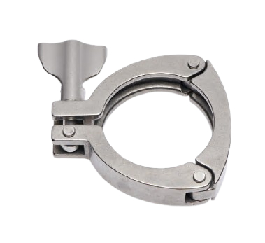
The three-segment design distributes closure over three arcs connected by cold-formed rivets. The clamp bears on the flanges at three points instead of two and opens wider for the same diameter.
Advanced Coupling clamp specifications
Single-screw, riveted hinges, 1″ to 4″, DN25 to DN100
Three-segment clamp hinged by rivets, 304L stainless steel body, single screw and wing nut. Five sizes from 1″ to 4″, i.e. DN25 to DN100, compatible with DIN 32676, ISO 2852 and ASME BPE ferrules. Maximum allowable pressure from 21 bar at 1″ to 12 bar at 4″. Designed for one-handed installation at points that are opened and closed often.
Why three segments
The opening is wider and the clamp stays in one piece once opened. It is positioned on the ferrule without any shell having to be held, and closes with one hand. On a point dismantled several times a day, this is the difference between a one-person operation and a two-person job.
The three segments bear on three arcs, which centres the clamp without intervention and avoids pushing the gasket during closure. Cold-formed rivets retain their hinge clearance over time, unlike an add-on pin that deforms over thousands of cycles.
The trade-off is pressure rating. A single screw and three hinges cap the allowable load at 21 bar at 1″ and 12 bar at 4″. This clamp is intended for service connections, not for high-pressure lines.
Frequently asked questions
When should a 3-segment clamp be chosen rather than a single-screw double-hinge clamp?
When opening frequency takes priority over pressure. Sampling points, filter housings, sight glasses, hose connections, connections in congested areas where the operator has only one hand free. As soon as the operating pressure exceeds 12 bar at 4″, a double-hinge or double-screw clamp is required.
How do I choose the size?
On the outside diameter of the ferrule, dimension A, never on the tube DN. The range covers five flanges: 50.5 mm, 64 mm, 77.5 mm, 91 mm and 119 mm. The downloadable correspondence table gives the full equivalence.
Can the rivets be dismantled?
No. The segments are assembled with cold-formed rivets and the clamp is supplied assembled. It is a non-repairable part: a deformed segment or a marked rivet requires the clamp to be replaced.
Three segments: is it cleanable?
The clamp remains outside the process. The rivet overlap areas are potential retention points during external washing, as with any hinge. On points subject to regular manual cleaning, the polished finish limits dirt adhesion.
304L or 316?
This range is produced in 304L. In chloride atmospheres, in wash rooms exposed to alkaline detergents or on halogenated solvent lines, a clamp available in 316 should be used instead.
What pressure should be used for a technical file?
That of the gasket under its actual operating conditions. The MAWP values correspond to the clamp alone, at ambient temperature.
Technical characteristics
304L stainless steel body, polished finish. Three segments, cold-formed rivets, one screw and a wing nut. Supplied assembled.
| Characteristic | Value |
| Type | 3 segments, single-screw, riveted hinges |
| Body material | 304L stainless steel |
| Closure | 1 screw, wing nut, 3 locating pins |
| Size range | 1″ to 4″ (DN25 to DN100) |
| Flange diameter | 50.5 / 64 / 77.5 / 91 / 119 mm |
| Band width | 19 mm at 1″ and 2″, 19.5 mm from 2 1/2″ to 4″ |
| MAWP | 21 bar at 1″ to 12 bar at 4″ |
| Compatible ferrules | DIN 32676 series A, B, C, ISO 2852, ASME BPE |
| Installation | One-handed, clamp stays in one piece when opened |
| Delivery | Assembled, ready to install |
| Packaging | Cardboard, plastic-free |
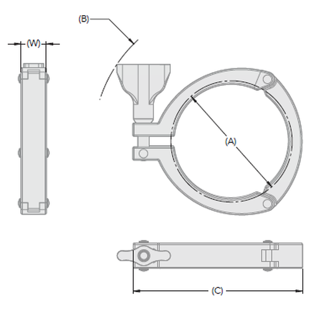
Dimensional drawing key: A flange diameter (ferrule face), B opening radius, C overall length, W band width.
Pressure rating
The maximum allowable pressure decreases with diameter. It applies to the clamp alone, at ambient temperature.
| Diameter | DN equivalent | Flange A (mm) | MAWP (bar) |
| 1″ to 1 1/2″ | DN25 to DN40 | 50,5 | 21 |
| 2″ | DN50 | 64 | 19 |
| 2 1/2″ | DN50 (ISO) | 77,5 | 15 |
| 3″ | DN65 | 91 | 12 |
| 4″ | DN100 | 119 | 12 |
The gasket, the sensitive link in the clamp fitting
The quality of a clamp connection depends on three elements: the gasket, the clamp and the alignment of the pipework.
The gasket provides sealing and at the same time absorbs the torsional loads transmitted by the pipework. This dual role is the weak point of the clamp fitting. A misaligned or stressed section makes the gasket work constantly, causing wear and then premature tearing.
On a point dismantled several times a day, the gasket is also the consumable. The clamp does not correct misalignment; it distributes the load. The gasket material, EPDM, silicone, FKM or PTFE, is chosen based on chemical compatibility and operating temperature.
The different types of clamps
The 3-segment clamp covers points with frequent opening and moderate pressure. The other versions address different constraints.
| Version | Closure | Use |
| 3 segments | 1 screw, 3 riveted segments | Frequent one-handed opening, from 21 to 12 bar, 1″ to 4″ |
| SH single-screw, double hinge | 1 screw, 2 axes | Standard connections from 50 to 10 bar, DN8 to DN300 |
| Reinforced double-screw SSH | 2 screws, 2 segments | High pressure, from 75 to 20 bar depending on diameter |
| Double hex nut | 1 screw, 2 nuts | Controlled and traceable tightening torque |
| Anti-opening safety | Shouldered eye bolt and grooved housing | Points where accidental opening under pressure must be prevented |
| Polymer, single-use | Quick closure | Bags, filters and disposable lines |