
SH 304L BV Double Hinge Cleanroom Clamp
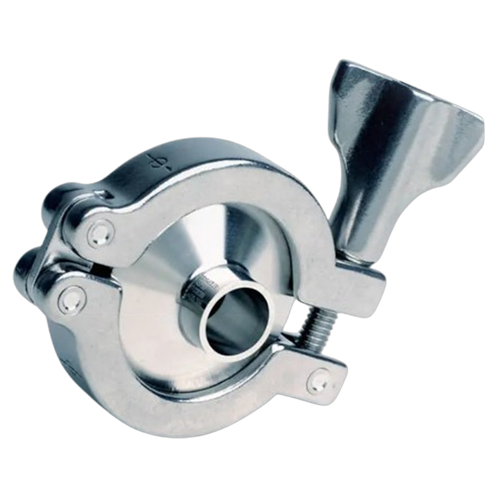
A clamp consists of two half-shells joined by a hinge and closed by a tightening mechanism. On a tri-clamp connection, sealing is achieved by compressing the gasket between the two ferrule faces. The clamp holds this compression and determines how it is distributed around the gasket circumference.
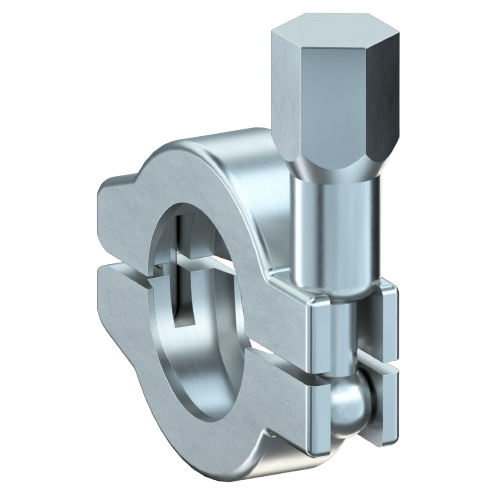
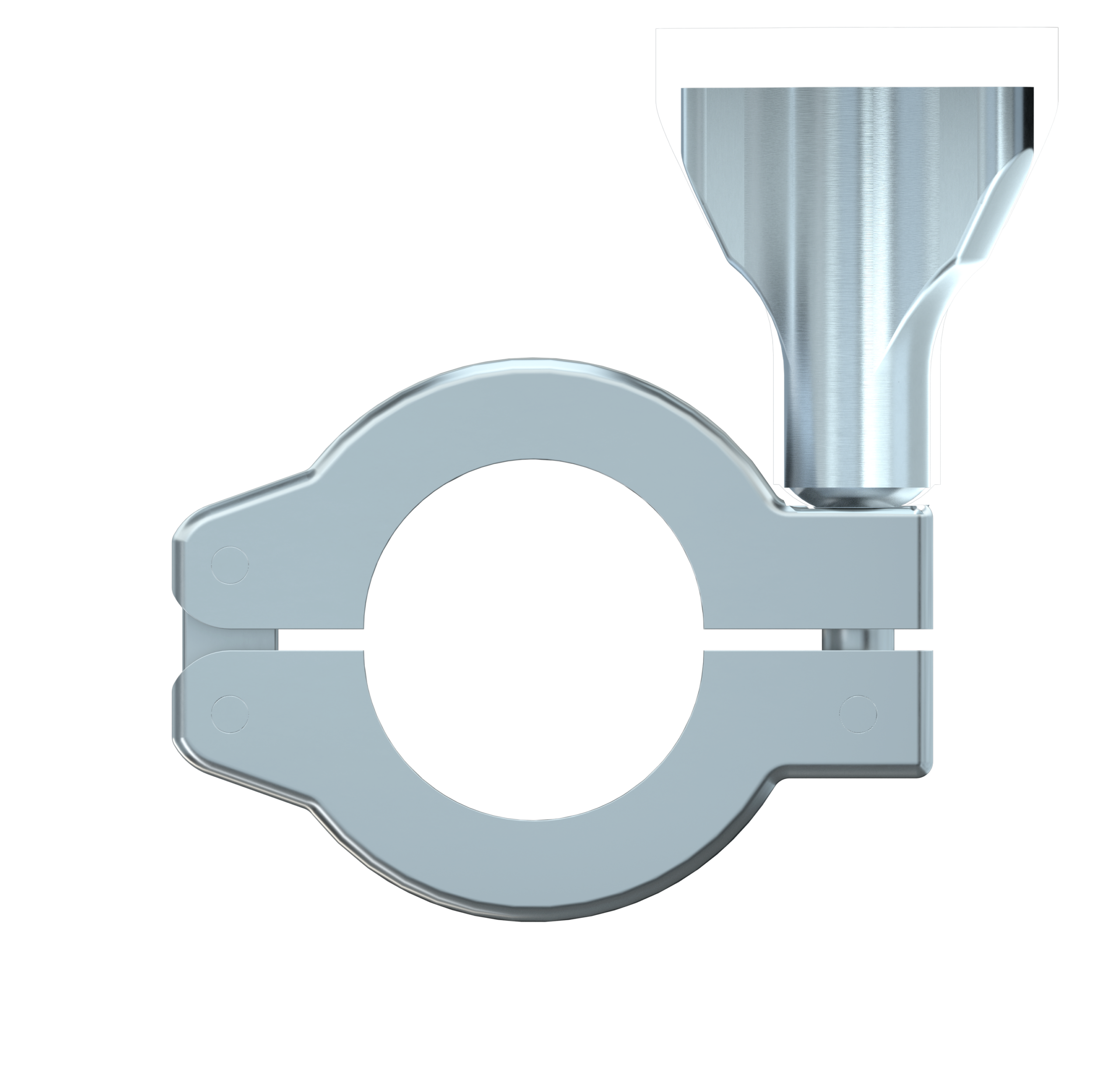
On this model, both hinges are integrated within the band thickness. No rivet protrudes from the outer profile. The clamp can be fitted and closed where a clamp with add-on hinges will not fit.
Dockweiler installation specification
Compact SH 304L BV clamps, non-protruding hinges
Integrated double hinge, wing nut, DIN 32676, ISO and ASME BPE
The SH 304L BV double-hinge clamp whose pins do not protrude beyond the band profile. 304L stainless steel body, 316 version available. Compatible with DIN 32676, ISO 2852 and ASME BPE ferrules, in imperial, ISO and metric dimensions. Connection rated up to 16 bar per DIN 32676, from -60 °C to +200 °C depending on the gasket. Hand-tightened to 5 to 7 Nm. Intended for instrumentation tappings and fittings in congested areas.
The protruding rivet, and the fitting you cannot install
On a conventional double-hinge clamp, the pins are formed by add-on rivets that protrude several millimetres from the outer face of the band. On an unobstructed line, nobody notices.
On an instrumentation tapping, they do. A pressure sensor, a temperature probe or a sampling point is always mounted on the shortest possible section, to limit dead legs and bring the measurement closer to the process. The ferrule ends up a few millimetres from the main tube, the neighbouring tapping or the frame wall. The rivet hits an obstacle before the clamp is in place.
You know what comes next: remove the instrument, take off the support, rework the loop by lengthening the tapping, or end up fitting a single-hinge clamp and accepting everything that implies for the gasket.
Integrated hinges eliminate the problem at source. The clamp’s outer profile is continuous, with no protrusion, and its envelope is limited to the band width and the tightening mechanism. The clamp sits flat against an obstacle, closes without lateral clearance, and retains the parallel closing motion of a double hinge.
Where this makes a difference
Measurement tappings on process piping, short instrumentation loops, sampling manifolds, connections for transmitters and thermowell probes, connections at the bottom of a skid or against a mounting plate, tightly packed racks where centre distances are fixed by the structure.
In refurbishments, this is often the only way to rework an existing connection without touching the piping. The section was welded short fifteen years ago, it holds, it is qualified, and nobody wants to redo it because of a clamp problem.
5 to 7 Nm, by hand, tool-free
The installation instructions specify hand-tightening of the wing nut to between 5 and 7 Nm, and explicitly prohibit the use of pliers or any other gripping tool.
That is not much, and it is deliberate. A clamp fitting does not seal through tightening force but through the face geometry and the controlled creep of the gasket in its groove. Beyond the specified torque, the gasket is pushed into the tube bore, forms a bead in the flow path and creates the dead leg the whole design was trying to avoid. Pliers turn a sanitary fitting into a retention point.
Few manufacturers publish this value. Including it in operator training and displaying it at reassembly stations saves more gaskets than any procedure.
Alignment, quantified
The instructions set two installation tolerances: axial misalignment of the tube ends of less than 0.5 percent of the outside diameter, and angular misalignment limited in the same proportion.
On a tube with a 25.4 mm outside diameter, that represents 0.13 mm. On a DN100 tube, 0.5 mm. In other words, almost nothing.
This is the quantified expression of what every fitter observes in the field: the gasket of a clamp fitting provides the seal and at the same time absorbs the torsional forces transmitted by the piping. A stressed section makes it work constantly, causing wear and then premature tearing. The clamp does not compensate for misalignment; it distributes the load.
Material
Clamp body in 1.4301, equivalent to UNS S30400, or in 1.4401, equivalent to UNS S31600. Manufactured under a DIN ISO 9001 certified quality system.
304 covers utilities, steam, compressed air and most process lines. 316 is justified in chlorinated atmospheres, at the seaside, in washrooms exposed to alkaline detergents and on halogenated solvent lines.
The associated ferrules are made in 1.4435, equivalent to UNS S31603, and meet the requirements of BN2, AD W2, DIN 17440 and ASTM 279. They carry dot-peen marking: material, heat number, manufacturer reference and size.
Operating conditions
The connection is rated from 0 to 16 bar per DIN 32676, and from -60 °C to +200 °C depending on the gasket material selected.
| Parameter | Value |
| Allowable pressure | 0 to 16 bar (232 psi), per DIN 32676 |
| Allowable temperature | -60 °C to +200 °C, depending on the gasket material |
| Fluids | Liquids and gases, ultra-pure media |
| Tightening torque | 5 to 7 Nm, by hand, tool-free |
| Axial misalignment | 0.5 percent max of tube outside diameter |
| Angular misalignment | 0.5 percent max of the absolute dimension |
The 16 bar value is that of the complete connection as defined by DIN 32676, not that of the clamp alone. It covers the ferrule, the gasket and the clamp. A clamp calculated for more does not raise the ceiling of the standardised connection.
If the allowable pressure is exceeded by more than 10 percent, or the temperature range is exceeded, the connection must be inspected before being returned to service.
Standards compatibility
The clamp is defined by the outside diameter of the ferrule face, not by the tube DN. It applies to ferrules made to DIN 32676, ISO 2852 and ASME BPE, in imperial, ISO and metric dimensions, provided the flange diameter matches.
The nominal wall thickness of the ferrules follows ISO and DIN 32676:2009-05. Conformity assessment is established under the Pressure Equipment Directive and ASME BPE. Connections in this category do not require marking under the Directive.
The gasket
The gasket is placed by hand between the two ferrules, centred and flush in the groove. Its inside diameter must neither protrude into the flow path, which creates an obstruction and retention, nor sit back from the face, which opens a crevice. Both defects are visible to the eye and are corrected before closing.
Installation is carried out with gloves, without any sharp-edged metal object. A gasket that is marked, nicked or contaminated by grinding dust or pickling residues is replaced, not salvaged.
The gaskets are available in several materials, with or without lip, cleaned to reduce residual organic contamination and laser-marked. The material is selected based on chemical compatibility and operating temperature. It is the material that sets the allowable temperature of the connection, not the clamp.
Opening under pressure
Opening a clamp fitting that is still under pressure is prohibited. The prescribed procedure is as follows: shut off and vent the line to atmosphere, check with a pressure gauge, then loosen the clamp while leaving it in place to hold the ends, separate gradually and check for the absence of residual pressure before complete removal.
If a product leak is foreseeable on opening, the intervention falls under a specific operating procedure with personal protective equipment. At points where this risk is permanent, a delayed-opening safety version is the right choice.
Technical specifications
| Characteristic | Value |
| Type | SH, integrated double hinge, no protruding rivet |
| Body material | 1.4301 (UNS S30400) or 1.4401 (UNS S31600) |
| Closure | 1 bolt, wing nut |
| Tightening torque | 5 to 7 Nm, by hand, tool-free |
| Compatible ferrules | DIN 32676, ISO 2852, ASME BPE |
| Dimensions | Imperial, ISO and metric |
| Allowable pressure | 0 to 16 bar per DIN 32676 |
| Allowable temperature | -60 °C to +200 °C depending on the gasket |
| Quality system | DIN ISO 9001 |
| Other versions | ASME BPE single hinge, safety, MHP, hex nut |
Dimensional drawing key: A flange diameter (ferrule face), B opening radius, C overall length, W band width.
Clamp and ferrule correspondence
The clamp flange diameter A corresponds to the outside diameter of the ferrule face, not to the tube DN. A DN25 tube fitted with a 1″ ferrule takes a clamp with a 50.5 mm flange. The same DN25 fitted with a DIN ferrule takes a clamp with a 34 mm flange. The table below gives the equivalence between clamp size, ferrule size and tube diameter for the ASME BPE, DIN 32676 and ISO 2852 standards.
Other clamp versions
This version addresses a space constraint. The others address different constraints.
| Version | Closure | Use |
| SH integrated hinges | 1 bolt, 2 non-protruding pins | Instrumentation, short tappings, congested areas |
| ASME BPE single hinge | 1 bolt, 1 pin | Connections installed once, BPE version |
| Safety, delayed opening | Shouldered eye bolt | Points where accidental opening under pressure must be prevented |
| Hex nut | 1 bolt, wrench | Controlled, traceable torque tightening |
| MHP | Reinforced | Higher-pressure connections |
Frequently asked questions
Why does this clamp fit where another will not?
Because its hinge pins are integrated within the band thickness instead of being formed by add-on rivets. The outer profile is continuous. On a short tapping, a tightly packed rack or a plate-mounted assembly, it was those few millimetres of rivet that prevented the clamp from reaching its position.
What tightening torque should be applied?
5 to 7 Nm, by hand, on the wing nut. The use of pliers or a gripping tool is prohibited. Excessive tightening pushes the gasket into the flow path and creates a dead leg.
Why only 16 bar?
It is the ceiling of the standardised clamp connection per DIN 32676, not the mechanical limit of the clamp alone. The value covers the ferrule, the gasket and the clamp. A clamp calculated for a higher load does not raise this ceiling once the fitting is declared compliant with the standard.
304 or 316?
304 covers utilities, air, steam and most process lines. 316 is required in chlorinated atmospheres, at the seaside, in washrooms exposed to concentrated alkaline detergents and with halogenated solvents. Both grades are available.
What alignment tolerance must be respected?
Axial misalignment of less than 0.5 percent of the tube outside diameter, i.e. 0.13 mm on a 25.4 mm tube. Beyond that, the gasket works under constant shear and tears prematurely.
How do I choose the size?
The choice is based on the outside diameter of the ferrule, dimension A. The tube DN is not enough: a DN25 exists with a 34 mm ferrule and with a 50.5 mm ferrule, depending on the standard.
Can a fitting be opened while still under pressure?
No. The line must be isolated and vented to atmosphere, with a pressure gauge check. The clamp is then loosened while remaining in place to hold the ends, and removed after checking for the absence of residual pressure.