
SH 316 Double Wing Bolt Clamp
Advanced Coupling Clamp Specifications
A clamp consists of two half-shells joined by a hinge and closed by a tightening mechanism. On a tri-clamp connection, sealing is achieved by compressing the gasket between the two ferrule faces. The clamp holds this compression and determines how it is distributed around the gasket circumference.
The double-bolt design distributes tightening over two diametrically opposed points, with adjustable-length swing bolts. The range starts at 2 1/2″ and the maximum allowable pressure ranges from 50 bar to 16 bar depending on the diameter.
Adjustable-length swing bolts, 2 1/2″ to 10″, DN50 to DN250
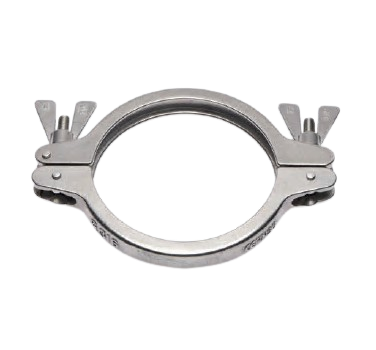
SH 316 clamp with double adjustable-length swing wing bolts, 316 stainless steel body. Diameters from 2 1/2″ to 10″, i.e. DN50 to DN250, compatible with DIN 32676, ISO 2852 and ASME BPE ferrules. Maximum allowable pressure from 50 bar at 2 1/2″ to 16 bar at 10″, calculated to ASME VIII Div. 1 App. 24. Wing nut or hex nut. Delivered assembled, partial dismantling possible during maintenance.
Two bolts, for tightening, not for pressure
Counter-intuitive but verifiable in the table below: the maximum allowable pressure of this clamp is exactly the same as that of the single-bolt clamp of the same diameter. 50 bar at 2 1/2″, 30 bar at 6″, 16 bar at 10″. Adding a bolt does not increase the MAWP.
What the second bolt changes is how compression is achieved. On an 8″ single-bolt clamp, all the force goes through one stud located opposite the hinge, and the operator works at the end of a 350 mm lever arm. With two opposing bolts, tightening is done alternately, as on a flange. The clamp closes in parallel, without one side getting ahead of the other.
The result is measurable on the gasket: uniform compression over the full 360 degrees, achieved without arm strength. This is also what makes tightening repeatable from one operator to another, a prerequisite as soon as a point is qualified.
This is why the range starts at 2 1/2″. Below that size, a single bolt is sufficient and quicker to operate.
Double adjustable-length swing bolts
The bolts are mounted as swing bolts, not through-bolts. They swing out sideways from their seat instead of being withdrawn from a bore. A slight misalignment of the two half-shells therefore does not prevent closing, whereas a through-bolt requires exact positioning before the thread can be engaged.
The effective length of each bolt is adjustable. This makes it possible to take up the accumulated tolerances of the two ferrules, particularly when they come from different suppliers or standards, and to obtain the same tightening travel on both bolts.
The clamp allows partial dismantling. The components stay attached to the shell during the intervention instead of ending up on the floor or in a toolbox. In a maintenance campaign with fifty fittings opened, this detail adds up to parts not lost.
Material and surface finish
316 stainless steel body.
The clamp remains outside the process and comes into contact neither with the fluid nor with internal CIP solutions. It is, however, exposed to floor washdowns, ambient steam, splashes of alkaline detergents and, in microelectronics, acidic atmospheres. The surface finish and grade 316 limit the onset of crevice corrosion in the overlapping areas of the hinges.
The fasteners are available in a galling-resistant version. On a two-bolt clamp, a galled thread on one of the bolts forces you to strain on the other, which unbalances the compression even before opening.
Pressure rating
The maximum allowable pressure depends on the diameter. It is calculated to ASME VIII Division 1, Appendix 24, and applies to the clamp alone.
| Diameter | DN equivalent | Flange A (mm) | MAWP (bar) |
| 2 1/2″ | DN50 (ISO) | 77,5 | 50 |
| 3″ and 3 1/2″ | DN65 and DN80 | 91 and 106 | 40 |
| 4″ | DN100 (DIN) | 119 | 35 |
| 4 1/2″ to 6″ | DN100 (ISO) to DN125 | 130 to 167 | 30 |
| 6 5/8″ | DN150 | 183 | 25 |
| 8″ and 8 5/8″ | DN200 | 217.4 and 233.5 | 20 |
| 10″ | DN250 | 268 | 16 |
The allowable pressure of the complete assembly depends on the gasket, its material, the operating temperature and the ferrule tolerances. The values in the table are the mechanical limit of the clamp at ambient temperature, not that of the connection.
Standards compatibility
The clamp is defined by the outside diameter of the ferrule face, not by the tube DN. It therefore applies equally to ferrules made to DIN 32676 series A, B and C, ISO 2852 and ASME BPE, provided the flange diameter matches.
Depending on the case, the associated tubes conform to DIN 11850, EN 10357 series A to C, DIN 11866 or ISO 2037. The hygienic classes H3, H4 and H5 of DIN 11866 make it possible to trace the correspondence between tube, fitting and internal surface finish.
Gasket selection
The clamp is independent of the gasket. The elastomer material, EPDM, silicone, FKM or PTFE, is selected based on chemical compatibility and operating temperature, then on the food or pharmaceutical compliance requirements applicable to the project. It is this choice that sets the allowable temperature of the connection, not the clamp.
On large diameters, the gasket is also the part least tolerant of asymmetrical tightening. Higher compression on one side than the other causes it to creep locally and creates a leak that no extra turn of the bolt can fix.
Overall dimensions
Band width of 19 mm from 2 1/2″ to 5″, 24 mm from 5 1/2″. Overall length from 124 mm to 382 mm depending on size. Flange diameter from 77.5 mm to 268 mm. As the two bolts are diametrically opposed, allow clearance on both sides of the fitting, not just one.
Applications
Pharmaceutical and biotechnology industries, PW (purified water) and WFI loops, process lines, solvent distribution, microelectronics, cosmetics, food processing.
A design in service for more than 30 years, optimised for installation and maintenance. Periodic inspections by third-party bodies. Clamps calibrated from batch to batch to ensure consistent fit on the ferrule. Packed in cardboard, plastic-free.
Technical specifications
| Characteristic | Value |
| Type | SH double bolt, adjustable-length swing bolts |
| Body material | 316 stainless steel |
| Fasteners | 2 swing eye bolts, wing nut or hex nut |
| Option | Galling-resistant fastener version |
| Size range | 2 1/2″ to 10″ (DN50 to DN250) |
| Flange diameter | 77.5 mm to 268 mm |
| Band width | 19 mm up to 5″, 24 mm from 5 1/2″ |
| MAWP | 50 bar at 2 1/2″ to 16 bar at 10″, ASME VIII Div. 1 App. 24 |
| Compatible ferrules | DIN 32676 series A, B, C, ISO 2852, ASME BPE |
| Maintenance | Partial dismantling possible, components remain attached |
| Delivery | Assembled, ready to install |
| Packaging | Cardboard, plastic-free |
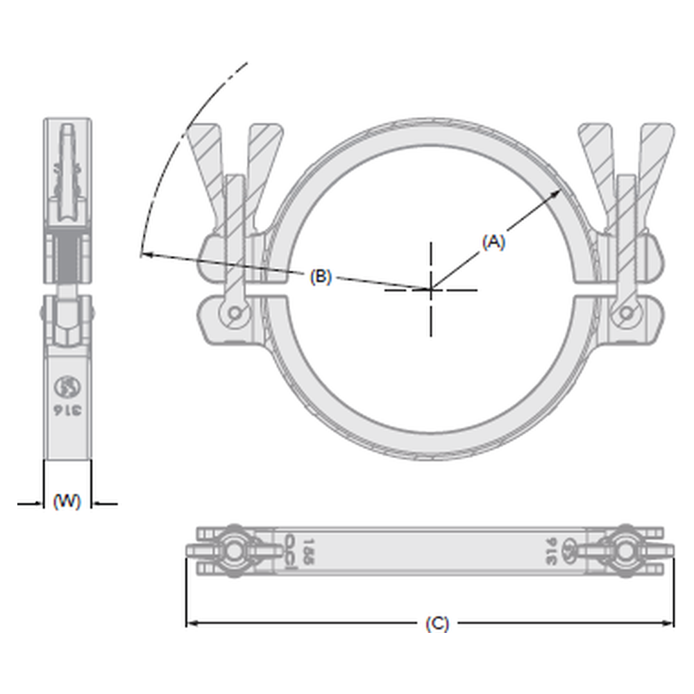
Dimensional drawing key: A flange diameter (ferrule face), B opening radius, C overall length, W band width.
Clamp and ferrule correspondence
The clamp flange diameter A corresponds to the outside diameter of the ferrule face, not to the tube DN. A DN65 tube fitted with a 3″ ferrule takes a clamp with a 91 mm flange. The table below gives the equivalence between clamp size, ferrule size and tube diameter for the ASME BPE, DIN 32676 and ISO 2852 standards.
Other clamp versions
The double bolt meets the need for symmetrical, repeatable tightening on medium and large diameters. The other versions meet different requirements.
| Version | Closure | Use |
| SH double eye bolt | 2 adjustable swing bolts | Symmetrical, repeatable tightening, 2 1/2″ to 10″, from 50 to 16 bar |
| SH single bolt, double hinge | 1 bolt, 2 pins | Standard connections from 50 to 10 bar, DN8 to DN300, quick operation |
| Double hex nut | 1 bolt, 2 nuts | Controlled, traceable torque tightening |
| Reinforced SSH | 2 bolts, 2 separate segments | High pressure, from 75 to 20 bar depending on diameter |
| Safety, 4 levels | 1 shouldered eye bolt, 2 pins | Points where accidental opening under pressure must be prevented |
| Three segments | 1 bolt, 3 riveted segments | Frequent one-handed opening, from 21 to 12 bar, 1″ to 4″ |
| Polymer, single-use | Quick closure | Bags, filters and disposable lines, -70 °C to 60 °C |
Frequently asked questions
Two bolts: does it withstand more pressure?
No. The MAWP is identical to that of the single-bolt clamp of the same diameter. The second bolt provides symmetrical, repeatable tightening without arm strength on large diameters. To go higher in pressure, you need to switch to a reinforced clamp.
How does it differ from a reinforced double-bolt clamp?
The reinforced clamp is designed for load and goes up to 75 bar on small diameters, in 304L. This one is a process clamp in 316L, which takes the pressure values of the SH and adds tightening quality. Two distinct needs, two products.
Why does the range start at 2 1/2″?
Below that, the lever arm stays short and a single bolt achieves the same compression more quickly. The double bolt is justified when the diameter makes single-point tightening uneven or difficult, i.e. from a 77.5 mm flange upwards.
What is the bolt length adjustment for?
To take up the accumulated tolerances of the two ferrules and obtain the same tightening travel on both bolts. Useful when the two ferrules do not come from the same standard or the same supplier.
Wing nut or hex nut?
The wing nut suits connections dismantled by hand in production. The hex nut is chosen when a tightening torque must be applied and recorded, particularly on points subject to qualification. The two bolts are then tightened alternately, in passes.
How do I choose the size?
The choice is based on the outside diameter of the ferrule, dimension A. The tube DN is not enough: a DN100 exists with a 119 mm ferrule and with a 130 mm ferrule, depending on the standard.
Which pressure should be used for a technical file?
That of the gasket under its actual operating conditions. The stated MAWP value applies to the clamp alone, at ambient temperature.