
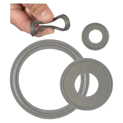


Tuf Steel FDA USP Class VI Clamp Gasket
On a tri-clamp connection, sealing is not provided by the clamp but by the gasket. The clamp sets the compression; the gasket turns it into a seal and absorbs the forces from the line. The choice of its material determines the allowable temperature, chemical compatibility and service life of the connection.
Tuf-Steel fills PTFE with 50 percent atomised 316L stainless steel. This filler gives PTFE the mechanical strength it lacks: no more creep, no more cold flow, and resistance from -196 °C to +288 °C. It is the most resistant gasket in the range.
Rubber Fab materials and chemical compatibility guide
Tubes Technologies gasket selection guide
Rubberfab references, Tuf Steel gasket
Guidelines for sanitary gasket materials
PTFE / 316L blend, -196 °C to +288 °C, creep-resistant
Tuf Steel clamp gasket, a proprietary 50/50 blend of unpigmented PTFE and atomised passivated 316L stainless steel. Service range from -196 °C to +288 °C, the widest in the range. The stainless steel filler eliminates PTFE creep and cold flow. Metal-detectable. USP Class VI compliant. Diameters from 1/2″ to 12″. The reference gasket for intensive SIP and WFI.
Where this material is the right choice, and where it is not
Tuf-Steel combines the chemical inertness of PTFE with a mechanical strength that solid PTFE lacks. The 316L stainless steel filler eliminates the creep and cold flow that make solid PTFE leak under thermal cycling. It does not flow back into the tube inside diameter, does not shrink, and holds without re-tightening under intensive SIP as well as in WFI. Its range of -196 °C to +288 °C is the widest in the range, opening it up to steam, hot oil and cryogenic points. It is metal-detectable, an asset in food processing. Backed by a decade of documented use.
Tuf-Steel is among the most expensive gaskets in the range. Its stainless steel filler reserves it for applications that genuinely use its mechanical strength and thermal range. On a cold-water line with no cycling or SIP, a standard PTFE or elastomer is sufficient and costs much less. Its compatibility with highly oxidising products must be checked, as for any filled PTFE.
Type I and Type II: the lip changes installation
Type I, or Type B, is a flat gasket without lip. It is centred by hand in the groove of the two ferrules. This is the most common and least expensive version.
Type II, or Type A, has a centring lip that fits into the inside diameter of the ferrule. The gasket positions itself, cannot shift while the clamp is being closed, and alignment of its inner face with the flow path is guaranteed. On lines where a shifted flat gasket creates retention, or on hard-to-reach installations, the lip eliminates the risk of poor centring.
The choice between the two does not depend on the material, which is identical, but on the centring requirement at the installation point. Both versions cover the same temperature range and the same chemical compatibility.
Material properties
| Characteristic | Value |
| Material | PTFE / 316L blend |
| Service temperature | -196 °C to +288 °C (-320 °F to 550 °F) |
| Composition | 50 percent PTFE, 50 percent atomised passivated 316L stainless steel |
| Creep | Eliminated, no cold flow or reversion |
| Detection | Metal-detectable |
| Compliance | FDA, USP Class VI, depending on size (see appendix) |
| Versions | Type I without lip, Type II with centring lip |
The temperature range and chemical compatibilities come from the manufacturer’s data. Detailed fluid-by-fluid chemical information is provided in the materials guide and the compatibility sheet, available for download.
Dimensions
Standardised dimensions, common to all tri-clamp gasket materials. The gasket outside diameter corresponds to the ferrule face, the inside diameter to the flow path. A gasket whose inside diameter protrudes into the flow path creates retention; a gasket that is too small opens a crevice.
| Size | Gasket ID (mm) | Gasket OD (mm) | Ferrule flange A (mm) | Tube DN |
| 1″ | 22,9 / 0.900″ | 50,4 / 1.984″ | 50,5 | DN25 |
| 1 1/2″ | 35,6 / 1.400″ | 50,4 / 1.984″ | 50,5 | DN40 |
| 2″ | 48,3 / 1.900″ | 63,9 / 2.515″ | 64 | DN50 |
| 2 1/2″ | 61,0 / 2.400″ | 77,5 / 3.050″ | 77,5 | DN65 |
| 3″ | 73,7 / 2.900″ | 90,9 / 3.579″ | 91 | DN65 |
| 4″ | 98,3 / 3.869″ | 118,9 / 4.682″ | 119 | DN100 |
| 6″ | 147,8 / 5.817″ | 165,3 / 6.507″ | 167 | DN150 |
Millimetre conversions are for guidance only, based on the manufacturer’s dimensions in inches. The complete clamp, ferrule and tube correspondence table is available for download.
The gasket: the sensitive link in the clamp fitting
The quality of a clamp connection depends on three elements: the gasket, the clamp and pipe alignment. The gasket provides the seal and at the same time absorbs the torsional forces transmitted by the line. This dual role is the weak point of the clamp fitting.
A misaligned or stressed section makes the gasket work constantly, causing wear and then premature tearing. Excessive tightening pushes the gasket into the flow path and creates a dead leg. Compression is achieved at the torque specified for the clamp, never by feel. The gasket is the consumable part of the connection: it is replaced, not salvaged.
This material compared with others
A gasket material is chosen based on temperature, fluid, dismantling frequency, regulatory requirements and cleaning method. Here is what sets the main materials apart.
| Material | What it offers | Its limitations |
| EPDM (and silicone) | Very flexible, seals even on irregular surfaces, easy to install, economical | Limited temperature, sensitive to solvents and oxidisers, does not withstand oils |
| FKM Viton | Solvents, oils, acids, up to 204 °C, ozone-resistant | Less effective with strong oxidisers, less flexible, more expensive |
| Solid PTFE | Exceptional chemical and thermal resistance | Very rigid, high tightening, possible creep |
| EPDM/PTFE enveloped | Inert PTFE face, flexible EPDM core, good compromise | Creep if overtightened, EPDM core limited in temperature |
| Gylon 3504 | Flexible, low tightening, creep-resistant, -260 to +268 °C | Flat without lip, care required during installation, blue |
| Tuf-Flex | PTFE bonded to EPDM, crush-resistant, WFI | More expensive, strong oxidisers to be checked |
| Tuf-Steel | PTFE + 316L stainless steel, creep-resistant, -196 to +288 °C | Expensive, reserved for demanding applications |
Each material has a dedicated data sheet with its service ranges, compliance and detailed chemical compatibilities.
Frequently asked questions
Tuf-Steel or Tuf-Flex?
Tuf-Steel for extreme temperatures and the most intensive SIP, with its stainless steel filler and range up to 288 °C. Tuf-Flex for maximum purity in WFI, with its PTFE surface bonded onto an elastomer core. The first is a gasket for strength, the second a gasket for purity and elastic memory.
Type I or Type II?
Type I, without lip, for standard installation. Type II, with centring lip, when the gasket must position itself and not shift, particularly where access is difficult or at points where shifting creates retention. Same material, same range; only the centring differs.
How do I choose the size?
On the outside diameter of the ferrule, like the clamp. The gasket inside diameter must be flush with the flow path without protruding. The correspondence table gives the equivalence between size, ferrule and tube.
Which compliance applies for pharmaceuticals?
FDA and USP Class VI compliance is stated by the manufacturer for sizes 1″ to 4″. Outside this range, it must be verified before being recorded in a file. The exact certification must appear on the material certificate for the batch delivered.