
HPX® Insert Disc Holder
A rupture disc is only as good as its holder.
Poorly centred, it opens outside its burst pressure.
Poorly tightened, it leaks.
Poorly designed, it fragments.
Continental Disc®’s HPX® Insert holder addresses all three: three centring pins, a conical metal-to-metal sealing seat, and a rounded outlet that guides the petal.
From DN 25 to DN 300, between ASME, DIN or JIS flanges, with a National Board certified flow resistance coefficient KR of 0.29 for gas.
HPX® Product Family brochure (PDF)
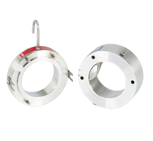
HPX® Insert, rupture disc holder between ASME, DIN and JIS flanges
Holder for HPX® and HPX®-Ta discs, DN 25 to DN 300, bubble-tight metal-to-metal sealing, KRG 0.29 and KRL 0.38 National Board certified, direct mounting under a safety valve up to DN 200
A two-part holder, inlet and outlet, fitted between the pipe flanges. It performs four functions: orienting the disc, sealing, protecting the dome during installation and preventing fragmentation on opening. Three alignment pins in the inlet orient the HPX® rupture disc. A conical seat on the inlet creates, when correctly installed, a bubble-tight metal-to-metal seal (no bubbles detected with leak detection fluid). The outlet bore has a radius that acts as a hinge for the petal: it rolls back without detaching.
The inlet protects the dome during fitting between flanges. Flow-direction arrows on the holder and on the disc tag confirm the orientation. An optional J-Hook orients the holder within its flanges. Flange faces with spiral serrations to ASME B16.5 as standard, i.e. a roughness of 3.2 to 6.3 µm Ra (125 to 250 micro-inches). Standard materials: carbon steel, 316 stainless steel, Alloy C276 and Alloy 400, others on request.
What it is for
The KR coefficient is the figure most often missing from a vent line design calculation. For the HPX® Insert holder and HPX® disc assembly, it is National Board certified: KRG 0.29 for gas or steam, KRL 0.38 for liquid. In a double holder, KRGL 0.97. These are low values, which leave the vent line sized by the piping and not by the safety device.
The 1″ to 8″ HPX® Insert holder can be coupled directly under a safety valve: disc upstream to isolate the valve from the fluid, no intermediate spool. At 10″ and 12″, a spool is required. The reduced-height HPX-RH version saves from 8 mm at 1″ to 89 mm at 8″ in height, but cannot be coupled directly under a safety valve.
When the flanges cannot provide the necessary compression (glass-lined or PTFE-lined flanges), or when the disc must be inspected in the workshop before installation, the HPX-PT® pre-torqued holder takes over. For highly corrosive media, the holder is lined or coated with tantalum and fitted with an HPX®-Ta disc.
Characteristics
| Characteristic | Value |
| Type | Holder to be inserted between flanges, inlet and outlet |
| Compatible discs | HPX® (HPX-90 and HPX-95), HPX®-Ta |
| Diameters | 1″ to 12″ (DN 25 to DN 300) |
| Flanges | ASME 150 to 1500, DIN PN 10 to PN 160, JIS 10 to 40K depending on diameter |
| Versions | Standard HPX® Insert, HPX-RH reduced height (1″ to 8″) |
| Disc / holder sealing | Metal-to-metal, bubble-tight, on conical seat |
| Disc centring | 3 alignment pins in the inlet |
| Anti-fragmentation | Hinge radius in the outlet bore |
| Orientation | Flow-direction arrows, optional J-Hook |
| Flange faces | ASME B16.5 spiral serrations, Ra 3.2 to 6.3 µm |
| Materials | Carbon steel, 316 SS, Alloy C276, Alloy 400 |
| National Board certified KR factor | KRG 0.29 (gas / steam), KRL 0.38 (liquid); KRGL 0.97 in double holder |
| Mounting under a safety valve | Direct from 1″ to 8″; spool required at 10″ and 12″; HPX-RH cannot be coupled |
| Coatings | Fluoropolymer, TANTALINE®, tantalum lining of the inlet |
Holder height and weight, ASME 150 flanges
Extract from the HPX® brochure: the height determines the spacing required between flanges.
| Diameter | Outside diameter (mm) | Insert / RH height (mm) | Insert / RH weight (kg) |
| 1″ (DN 25) | 63,5 | 45,7 / 37,3 | 0,9 / 0,7 |
| 1½″ (DN 40) | 82,6 | 51,8 / 42,4 | 2,0 / 1,2 |
| 2″ (DN 50) | 101,6 | 59,9 / 45,7 | 2,7 / 1,8 |
| 3″ (DN 80) | 133,4 | 81,5 / 55,6 | 5,4 / 3,6 |
| 4″ (DN 100) | 171,5 | 100,8 / 73,6 | 11 / 7,7 |
| 6″ (DN 150) | 219,2 | 143,3 / 92,5 | 20 / 13 |
| 8″ (DN 200) | 276,4 | 184,4 / 95,8 | 35 / 20 |
| 10″ (DN 250) | 336,6 | 155.4 / no | 40 / no |
| 12″ (DN 300) | 406,4 | 181.8 / no | 73 / no |
Options
J-Hook orientation hook. Fluoropolymer or TANTALINE® coating of the inlet, intermediate flange and/or outlet, tantalum lining of the inlet. Tell-tale assembly between disc and valve: ¼″, ⅜″ or ½″ pressure gauge tap threaded into the outlet, ¼″ or ½″ steel or stainless steel nipples and tees, 316 excess flow valve, pressure gauge. Studs and nuts in alloy steel (ASME SA-193-B7 / SA-194-2H) or stainless steel (SA-193-B8M Class 2 / SA-194-8M). Case-hardened steel jack screws (set of 3), lifting eyes. Cleaning for oxygen or chlorine service. Universal B.D.I.® burst sensor.
Frequently asked questions
Why a metal-to-metal seat rather than a gasket?
Because a gasket ages, creeps and must be chosen according to the fluid. A conical metal-to-metal seat depends neither on temperature nor on the chemical compatibility of an elastomer. It provides a bubble-tight seal as long as installation follows the torques in the installation manual. For a quantified leak rate requirement, Continental Disc carries out specific tests.
Standard Insert or reduced-height HPX-RH?
The HPX-RH saves height: 14 mm at 2″, 26 mm at 3″, 51 mm at 6″. Useful on existing piping where the spacing between flanges is restricted. On the other hand, it cannot be coupled directly under a safety valve and is not available in 10″ and 12″.
Can the holder be mounted directly under a safety valve?
Yes, from 1″ to 8″. The HPX® disc isolates the valve from the fluid, eliminates seat leakage and protects the internals. At 10″ and 12″, an intermediate spool is required to allow the petal to open without touching the valve.
How can you tell whether the disc is leaking or has burst under a safety valve?
With a tell-tale assembly: a pressure gauge and an excess flow valve in the space between the disc and the valve. A rise in pressure signals a leak or a burst. For an electrical signal to the PLC, the universal B.D.I.® sensor slides between the flanges.
What is the double-disc holder for?
Two HPX® discs in series in a single three-piece holder. Three uses: leak detection on toxic or expensive fluids (pressure gauge in the intermediate flange), a rapid-opening device actuated by depressurising the space between the discs in a few milliseconds, and elimination of the effect of back pressure on the first disc. KRGL 0.97.
Which studs should be used?
Studs of the correct length to take the inlet, holder and outlet, in ASME SA-193-B7 alloy steel with SA-194-2H nuts, or in SA-193-B8M Class 2 stainless steel with SA-194-8M nuts. Lower-strength studs may not achieve the clamping load required for sealing.